Quick Start for BB-MMx
Flashing the BB-MMx (MM1, MM2, MM3) board
SDK installation directory: In the commands below,
/path/to/mmwave_mcuplus_sdk_04_07_02_01refers to the directory where the SDK archive was installed. The MMWave SDK is normally inside itsmmwave_mcuplus_sdk_04_07_02_01/subdirectory, while the MCU+ SDK is alongside it. Replace this path with the actual installation directory on your system.
- Attach MM1 with MMB baseboard itself.
- There is no need to power the board directly through
J4as power can be supplied from USB. - You will need to change SOP mode to SOP0 = 1, SOP1 = 0, SOP2 = 1 for QSPI uart flash mode. To change between flash mode and normal mode requires that the
SOP2_PMIC_CLKpin is pulled high rather than pulled low. This is pin 3 onJ2connector.SOP2_PMIC_CLKis not pulled on the radar chip (it is a high impedance input at reset with no pull) and there are no other pullups / pull downs available. DepopR57to remove the only 10K pulldown. Use a pull up to 3.3V (10K resistor). UseVDDIO_3.3Vrail if possible, you can useTP15for this supply. Alternatively, can use3.3V_SYSrail or an external 3.3V so long as grounds are shared. - Power cycle the board if changed SOP mode.
- Connect a USB-A to PicoClasp 4 pin cable to
J3on the MMB board. - Connect the USB-A to a programming machine and confirm that you see the usb device appear. Use
lsusbanddmesgon GNU/Linux based distros orDevice Managerif using Windows. - Install the mmWave MCUplus SDK
mmwave_mcuplus_sdk_04_07_02_01-{operating_system}-Install.{exe|bin}here Note the difference if you are using a Linux-based or Windows system. I also have a link for a google drive of an unzipped archive tarball of the sdk here for the Linux build if you are having trouble extracting on a linux-based system. - Locate the rebuilt
/path/to/mmwave_mcuplus_sdk_04_07_02_01/ti/demo/awr2x44P/mmw_tdm/awr2x44P_mmw_demoTDMEnet.appimageand the MM1 SBL images undermcu_plus_sdk_awr2x44p_10_02_00_04/tools/boot/sbl_prebuilt/mm1/. These are different from the standard AWR2x44P EVM SBL images. - Install
Sysconfigfrom here as this is important if you later want to download tools like theMmwave_Demo_VisualizerandCCS Studiofor flashing updated code or debugging. - Install
CCS Studiofrom here
Make necessary edits for MM1 board
See MM1 Flash Configuration Patch for the copyable patch and build procedure.
Programming the board
Using Python
- Ensure
python3.9+is available. Runwhich pythonandpython --versionto confirm the version available
export MMWAVE_SDK_DEVICE=awr2x44P
Furthermore, check that MMWAVE_SDK_TOOLS_INSTALL_PATH, CCS_INSTALL_PATH, SYSCONFIG_INSTALL_PATH path are all correctly set based on your system.
For the MM1-based SBL builds, use the following /path/to/mmwave_mcuplus_sdk_04_07_02_01/tools/awr2x44P/default.cfg:
#-----------------------------------------------------------------------------#
#                                                                             #
#      DEFAULT CONFIGURATION FILE TO BE USED WITH THE FLASHWRITER SCRIPT      #
#                                                                             #
#-----------------------------------------------------------------------------#

# MM1 UART flash writer
--flash-writer=../../../mcu_plus_sdk_awr2x44p_10_02_00_04/tools/boot/sbl_prebuilt/mm1/sbl_uart_uniflash.release.tiimage

# MM1 QSPI SBL. ROM expects the bootloader at offset 0x0.
--file=../../../mcu_plus_sdk_awr2x44p_10_02_00_04/tools/boot/sbl_prebuilt/mm1/sbl_qspi.release.tiimage --operation=flash --flash-offset=0x0

# MMW application. The SBL expects the application at offset 0xA0000.
--file=../../ti/demo/awr2x44P/mmw_tdm/awr2x44P_mmw_demoTDMEnet.appimage --operation=flash --flash-offset=0xA0000
- Flash with
python /path/to/mcu_plus_sdk_awr2x44p_10_02_00_04/tools/boot/uart_uniflash.py -p <COM_PORT or serial device> --cfg=/path/to/mmwave_mcuplus_sdk_04_07_02_01/tools/awr2x44P/default.cfg - If this fails, which it often does, check that the board is definitely in UART flashing mode with the SOP configuration (usually the power will average 1.4W and stay at that relatively low value, the other way to test is to probe
SOP2directly).
Using UniFlash
- Install
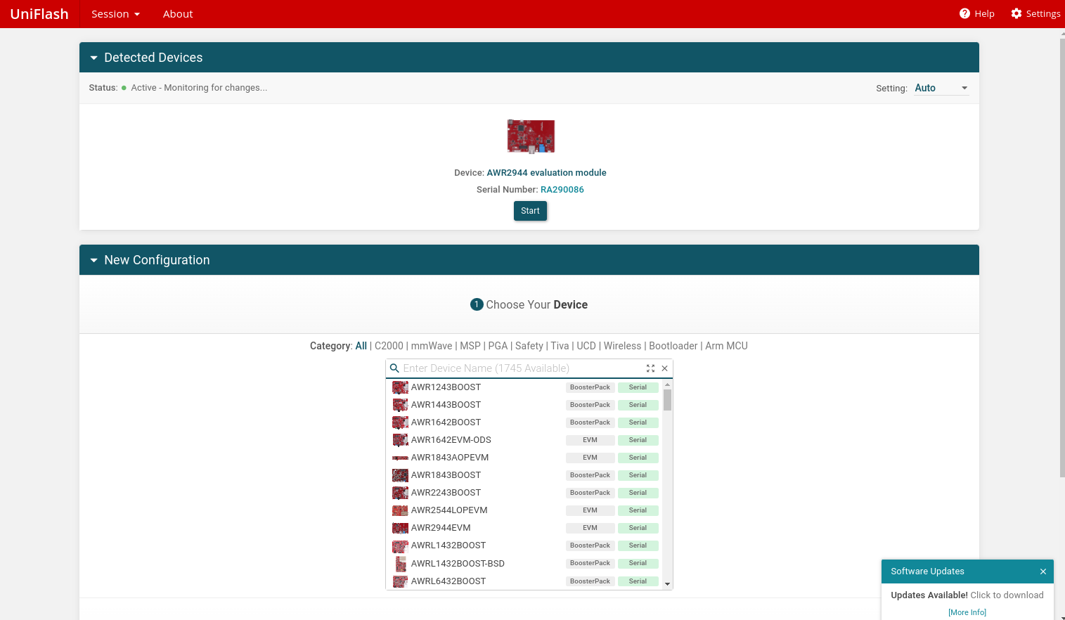
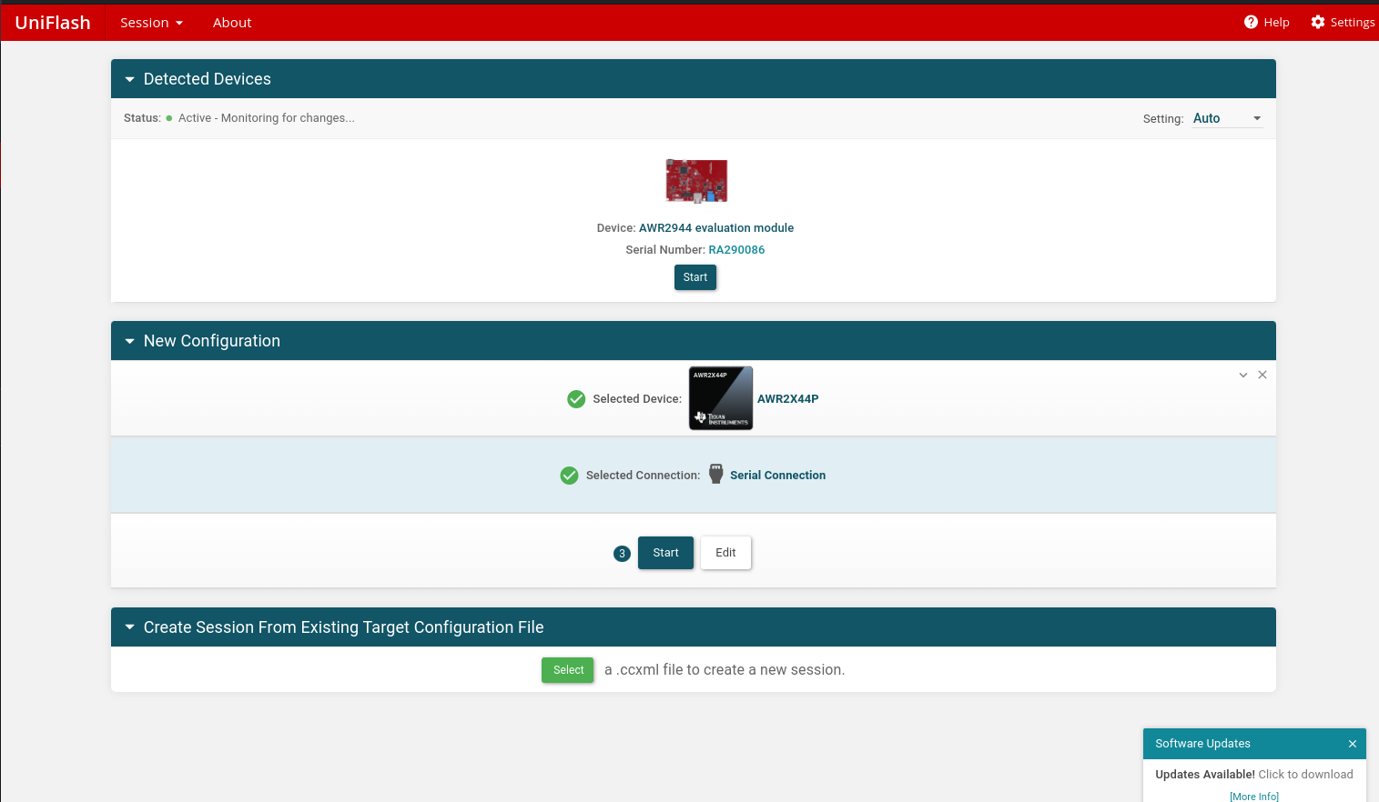
UniFlashfrom here - If you are programming the AWR2944EVM board, then select AWR2944EVM as device. For the
AWR2944P, choose aAWR2x44Pas the device with serial connection.
-
Select 'select and load images' when you find the devices.
-
For MM1, use the edited and rebuilt images from
mcu_plus_sdk_awr2x44p_10_02_00_04/tools/boot/sbl_prebuilt/mm1/:sbl_qspi.release.tiimageis the SBL image used by UniFlash.sbl_uart_uniflash.release.tiimageis the UART flash writer used byuart_uniflash.pyand referenced bydefault.cfg.
-
Upload the MM1
sbl_qspi.release.tiimageas the SBL image andawr2x44P_mmw_demoTDMEnet.appimageas the App Image for theAWR2944Pdevice. Useawr2944_mmw_demoTDMEnet.appimageas the App Image for the AWR2944EVM board. -
When ready, click
Load Image -
Once flash is sucessful, power off board and put it back into functional mode by removing pullup on pin 3 of
J2(SOP2) and repopulatedR57with 10K resistor OR use another MMB baseboard. -
You may get errors here and usually the troubleshooting involves trying a different machine (Linux/Windows), making sure that you plug in USB AFTER powering the board, or by making sure to trigger a reset (on the EVM board by pressing
SW1). On the MM1 board, you will need to trigger a reset with a JLink device onJ7or by configuringAR_NRST(pin 10 onJ7orTP30on the baseboard orTP13on the module board) with a switch that pulls it low.
Troubleshooting:
- If you receive
[ERROR] Cortex_R5_0: XMODEM send failed, it is likely that you forgot to correctly setup the SOP jumper pins for flashing mode. Refer to step 1. - If it takes forever to flash, unplug the USB and then power cycle the board. Make sure you plug in the USB AFTER power cycling the board.
Serial console check
You can open a console on the serial port corresponding to User/Application port to confirm whether the application boots and whether the CLI becomes available. On linux, check ls /dev/tty* to see which udev devices appear when the usb port is connected, and on windows check Device Manager for the COM ports available. This is a useful quick trick to see if the board was programmed and the SOP mode is configured to QSPI boot.
Configuration
Visualiser
- Set yourself up with
mmWave_Demo_Visualizerversion 4.7.0 here - You can download this on both Windows or Linux but I have had more success on the online version on Linux based systems.
- Open this on Chrome with the TI Cloud Agent chrome extension installed
- Go to
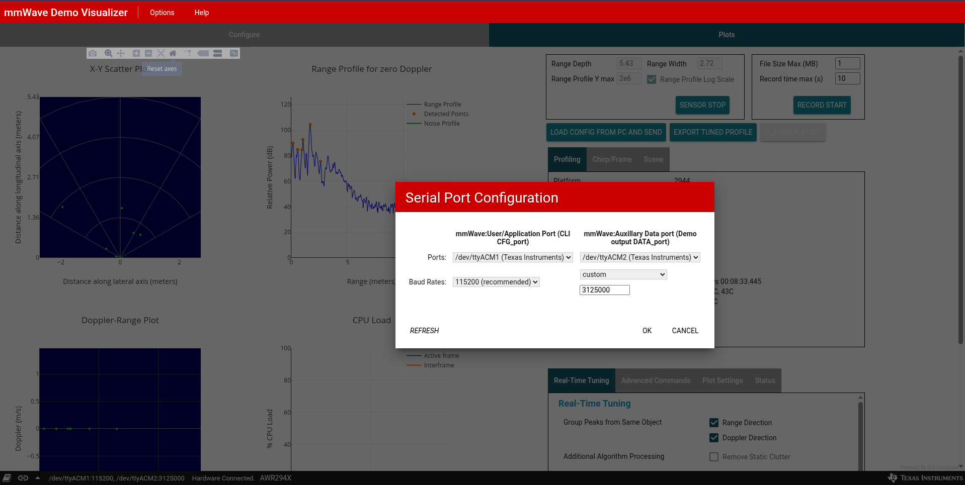
Options->Serial Portand configure theUser/Application portand theAuxillary Data port.
-
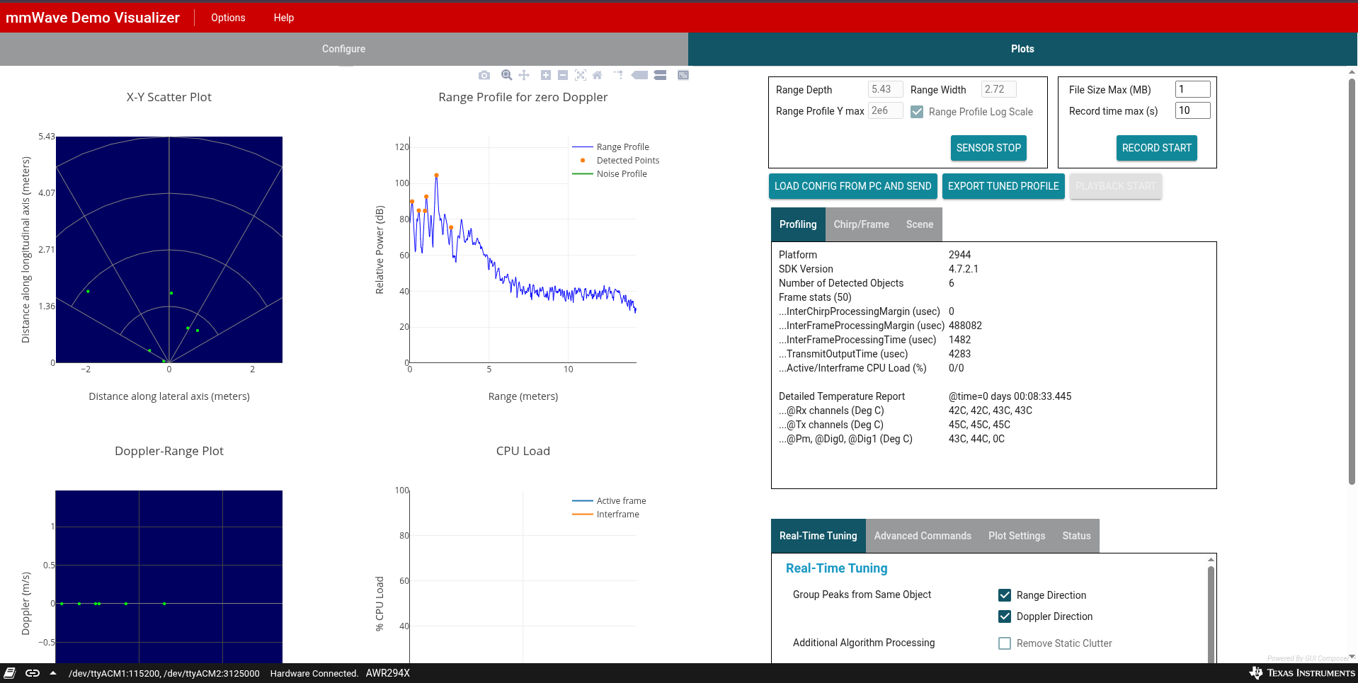
You should see in the bottom left corner whether the hardware has been detected or not. If it has not, power cycle, replug the USB interface or attempt to do a reset through
AR_NRSTwhilst connected to a power supply. -
Go to
Plots->Load config from PC and send. For an example profile configuration, navigate to/path/to/mmwave_mcuplus_sdk_04_07_02_01/mmwave_mcuplus_sdk_04_07_02_01/ti/demo/awr294x/mmw/profiles/tdm_awr2944/profile_Enet.cfgand load this. Note that this profile is for the 'wrong' chip (AWR2944 vs AWR2944P), so we will need to recreate a new one for our board in future. Though it seems to work. -
Note that the
profile_Enet.cfgonly outputs for 50 frames and then stops. Usemmwave_mcuplus_sdk_04_07_02_01/ti/demo/awr2x44P/mmw_tdm/profiles/awr2944P/profile_3d_3Azim_1ElevTx_awr2944P.cfg(ormmwave_mcuplus_sdk_04_07_02_01/ti/demo/awr294x/mmw/profiles/tdm_awr2944/profile_3d_3Azim_1ElevTx.cfggiven their similarity). -
These are just examples, you will need to perform calibrations before actually testing the board.
Antenna geometry configuration
For BB-MM1 board, we have a virtual antenna array of 16 elements.
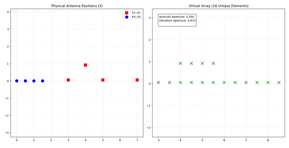
Hence all profile configurations must use this antenna geometry.
antGeometryCfg 1 0 1 1 1 2 1 3 0 2 0 3 0 4 0 5 1 4 1 5 1 6 1 7 1 8 1 9 1 10 1 11 0.5 0.87
Antenna calibration for TDM mode
The output from loading the default profile and starting the sensor will mean almost nothing because calibration has not been performed.
The calibration procedure measures range bias and receive-channel gain/phase errors. It is supported here for TDM operation. This calibration isn't due to some fault in the design but rather there are always imperfections in antenna layouts on the board, RF delays in the SOC, etc. There is a need to calibrate the sensor to compensate for bias in the range estimation and receive channel gain / phase imperfections. This will need to be done on EVERY BB-MM1 board, even if the revision has not changed.
- Place a strong corner reflector at a known distance
Xmetres from the radar, directly on boresight. Do not use a distance below approximately0.5metres. - Copy this into a new calibration profile below into
mmwave_mcuplus_sdk_04_07_02_01/ti/demo/awr2x44P/mmw_tdm/profiles/awr2944P/profile_calibration.cfg
% Calibration config
sensorStop
flushCfg
dfeDataOutputMode 1
channelCfg 15 15 0 0 0
adcCfg 2 0
adcbufCfg -1 1 1 1 1
lowPower 0 0
profileCfg 0 77 7 3 39 0 0 100 1 256 7200 0 0 158
chirpCfg 0 0 0 0 0 0 0 1
chirpCfg 1 1 0 0 0 0 0 4
chirpCfg 2 2 0 0 0 0 0 8
chirpCfg 3 3 0 0 0 0 0 2
frameCfg 0 3 32 0 256 500 1 0
guiMonitor -1 1 1 1 1 0 1
cfarCfg -1 0 2 8 4 3 0 15.0 0
cfarCfg -1 1 0 4 2 3 1 15.0 0
multiObjBeamForming -1 1 0.5
calibDcRangeSig -1 0 -5 8 256
clutterRemoval -1 0
antGeometryCfg 1 0 1 1 1 2 1 3 0 2 0 3 0 4 0 5 1 4 1 5 1 6 1 7 1 8 1 9 1 10 1 11 0.5 0.87
compRangeBiasAndRxChanPhase 0.0 1 0 1 0 1 0 1 0 1 0 1 0 1 0 1 0 1 0 1 0 1 0 1 0 1 0 1 0 1 0 1 0
measureRangeBiasAndRxChanPhase 1 1.5 0.2
aoaFovCfg -1 -90 90 -38 38
cfarFovCfg -1 0 0.25 8.64
cfarFovCfg -1 1 -7.06 7.06
extendedMaxVelocity -1 0
calibData 0 0 0x1f0000
sensorStart
Note the values for measureRangeBiasAndRxChanPhase. The first number is 1 to enable the calibration measurements, second is the distance from the boresight (0 degree azimuthal) of the corner reflector from the boresight, and the third is the size of the window along the range axis that the response peak of that corner reflector will be searched.
-
For example, the profile default contains a measurement command with the reflector distance and search window. For example, for a reflector at
1.5metres with a window of20centimetres:measureRangeBiasAndRxChanPhase 1 1.5 0.2
Please alter these with your desired values. Ensure that the window spans at least a few range bins. The range resolution is determined by the discrete bins of the FFT applied to the intermediate-frequency signal:
where c is the speed of light and B is the total measured bandwidth of the chirp.
-
Start the sensor and wait for the calibration result on the CLI port. The applications prints a
TDM: compRangeBiasAndRxChanPhase ...command containing the measured range bias and receive-channel coefficients. -
Copy the complete printed
compRangeBiasAndRxChanPhasecommand into the normal operating profile. Use that command with measurement disabled, for example:compRangeBiasAndRxChanPhase 0.0 1 0 1 0 1 0 1 0 1 0 1 0 1 0 1 0 1 0 1 0 1 0 1 0 1 0 1 0 1 0 1 0measureRangeBiasAndRxChanPhase 0 1.5 0.2
The generated compensation command must be retained with any profile used for actual operation. Set the first number of measureRangeBiasAndRxChanPhase with 0 from 1 if you do not wish to calibrate any further.
Other notes
aoaFovCfg -1 -90 90 -38 38 are the defaults but may need to be altered based on the desired angle of arrival limits. This is useful for cutting out any sidelobe detection that may arise. Consult the antenna response diagram.